Instruments: Zoom Lens Spectrograph
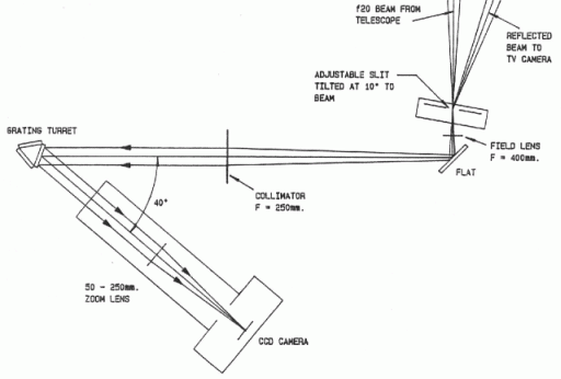
IntroductionThe medium dispersion spectrograph operates at the f/19 Cassegrain focus of the University telescope. The spectrograph is mounted below the perforated primary mirror. The optical layout of the spectrograph is given below.
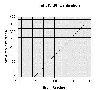
SlitThe beam from the telescope first encounters the slit of the spectrograph which is tilted at 10 degrees to the beam. The slit is adjustable from 0-500 microns in width by means of a multi-turn digital dial on the outside of the case. The dial is labeled SLIT. A calibration curve for the relationship between dial reading units and slit width in microns and arc seconds is given below. The desired drum reading can be calculated from the relationship:
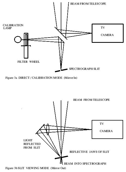
The jaws of the slit are very flat and highly polished which means that any light from the star which does not fall down the slit is reflected off and can be viewed by the TV camera. The optical arrangement for this is shown below. Thus during the process of taking the spectrum of a star it is possible to see the star image on the slit of the spectrograph by means of the TV camera.
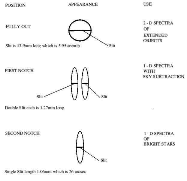
DekkerThis is a mask which can be moved in front of the slit to change the length of the slit which is illuminated. The DEKKER has three positions which can be selected by moving in or out the lever at the top of the spectrograph. The options for the Dekker are shown in the figure below. The double mask can used for sky subtraction.
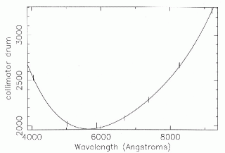
CollimatorThe distance between the camera lens in the spectrograph and the detector is fixed and any adjustments in the focus of the spectrograph must be made by moving the collimator lens relative to the slit. Both the collimator and zoom camera use lenses which suffer from chromatic aberration. Thus the optimum focus will be a function of wavelength, see below.
GratingsThere are three gratings available:
Grating AnglesThe angle between the collimator beam and the beam entering the camera is fixed at 40 degrees. To select the wavelength of interest we rotate the grating on a turntable by means of a digital dial on the outside of the case. The digital readout displays the angle of incidence of the collimated beam on the grating multiplied by 10. Since the angle of incidence + angle of diffraction must equal 40 degrees we can also deduce the angle of diffraction. Eg. if the digital dial reads 200 then i = 20.0 degrees and since i + r = 40.0 degrees then r = 20.0 degrees also. The case given as an example is in fact the special condition i = r = 20.0 where zero order would be central on the detector. The program ARCSPEC will predict the necessary grating angle i for all wavelength, grating and lens combinations. To enable the grating angles to be set up roughly the following angles will place the mercury green line near the centre of the spectrum on the detector.
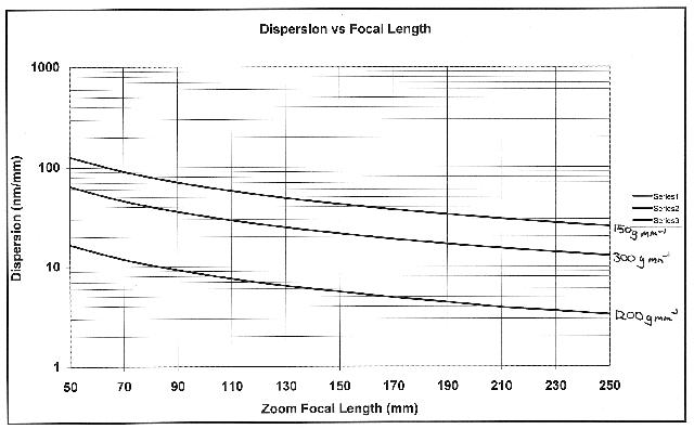
Camera Focal LengthThe spectrograph is provided with a zoom lens with a focal length which can be varied continuously within the range 50-250 mm. Thus for a particular grating the linear dispersion can be varied by a factor of five by use of the zoom lens. It also allows any particular dispersion to be selected from the graph on the figure above. Changing the focal length of the camera lens will, in addition to changing the spectral dispersion and resolution, also affect the width and length of the image of the slit as seen by the detector. Eg. The collimator has a focal length of 250 mm. If the camera lens is set to 250 mm then there will be a 1:1 relationship between the slit and its image at the detector. If however we use a camera focal length of 50 mm then the image of the slit will be reduced both in width and height by a factor of five. This is also calculated by the ARCSPEC program. |

